Trying to fight gravity
Here’s another project that was done in college. In one of my senior design classes, we had to build a project that just had a sensor of some kind. I was in a team with four other people, two were undergraduates like myself, and the other two were graduate students. One of the grad students came up with the idea of measuring the magnetic field intensity, and displaying the strength on an LCD screen. The idea was nice, but too basic for our liking. How would we, or the rest of the class know the measurement was even accurate? We had to come up with better idea.
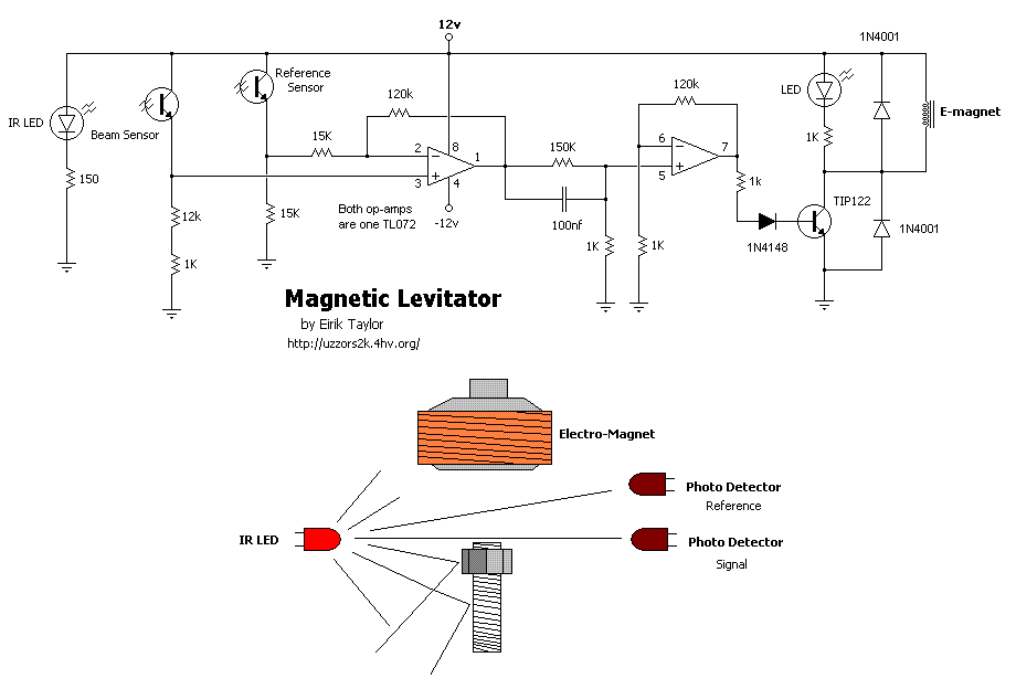
I remember seeing projects on instructables about levitating a magnet in the air using line break sensors to control an inductor, like the one in the picture below, and thought “why can’t we do this with a magnetic field sensor?” And so the idea was born.

We came across consumer products that did this and we wanted to try it ourselves. I took out my Arduino, and started writing some code. The concept was almost the same as the line break sensors:
We would read the analog voltage from the ratiometric hall effect sensor, and get set a set point. If the value exceeded the set point, cut power to the inductor, or if it was below the set point, turn the power back on to the inductor.
There was a problem with this approach though, it was inherently unstable. And didn’t work at all. Our experiments progressed, using pulse-width-modulation (PWM), here we would increase power until the force on the magnet exceeded the force of gravity, and then we would reduce power with each loop iteration until the magnet crossed back over the set point. This time it would hover for a second, before the magnet dropped to the table, or stuck to the inductor.
Our final iteration was successful. What we did was check if the magnet was in the range of the set point. Just as before, if the magnet was too close, we would reduce the duty cycle, and if it was too low, we would increase the duty cycle, but if it was in the “Goldilocks” range, we wouldn’t make any adjustments. Here are the results of our third experiment:
As you can see, there are still oscillations, but it was stable enough that it wouldn’t fall outside of the range we set. Here’s the original code we used to get it up and running, it’s incredibly simple.
// A0 - Hall Effect Sensor Output
// D5 - MOSFET Gate

byte pwmValue = 100;

void setup()
{
 TCCR0B = TCCR0B & 0b11111000 | 0x02; //Increase PWM frequency to 7.8kHz
 pinMode(5, OUTPUT); //sets digital pin 5 as Output and connect to gate of mosfet
}

void loop()
{
 int Hall=analogRead(A1); //0-1024
 if(Hall>920)  //if magnet is too high, reduce PWM until lower threshold is reached
 {
   pwmValue-=5;
   analogWrite(5,pwmValue);
 }
 else if(Hall<900) //if magnet is too low, increase PWM until upper threshold is reached
 {
   pwmValue+=5;
   analogWrite(5,pwmValue);
 }
}
If I were to build this again, there’s a couple of things I would want to add. The first, I would want to impliment a PID loop, to remove the oscillations and get smooth positioning. None of us in the group at the time really had any clue how to program, so a lot of the time was spent figuring out how to change the default PWM frequency and learn how to do embedded programming. The second change I would make would be to add in a second sensor on the other side of the inductor. The main problem with one sensor, is that you’re not only measuring the strength of the magnetic field from the magnet, but also the magnetic field from the inductor, which probably helped create some of the oscillations in the first place.