There’s just something so visually pleasing about seeing the orange glow from vintage nixie tubes. I’ve seen commercially available nixie clocks, and even kits, but they cheaper ones I’ve found are still a couple hundred dollars, so I decided I’d make my own. I’d like to start out by talking about why I work on my various projects. Each project I work on, starts with wanting to know more about a part or using a new type of technology. My pocket amplifier for example, I made because I had a need to increase the power from my iPod, but I also wanted to learn how to make my own circuit boards at home. This clock was my first experience with the ESP8266, and the whole reason I made this clock, was to be able to experiment with this board and scratch the surface at what it can do.
Get the files from Github
A few years ago I bought a VFD clock from Adafruit, but after a couple months the clock would be a few minutes slow. The reason for the drift comes from the crystal oscillator used to keep track of time, even with an accurate crystal, it wasn’t 100% accurate and the error would build each day, until it was a few minutes slow and needed to be reset. For my clock, I wanted to make sure that never happened, and that’s why I decided to use the ESP8266. The WiFi board will talk to a Network Time Protocol (NTP) server and retrieve the current time every day.
The Main Guts
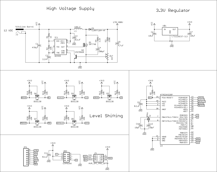
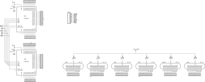
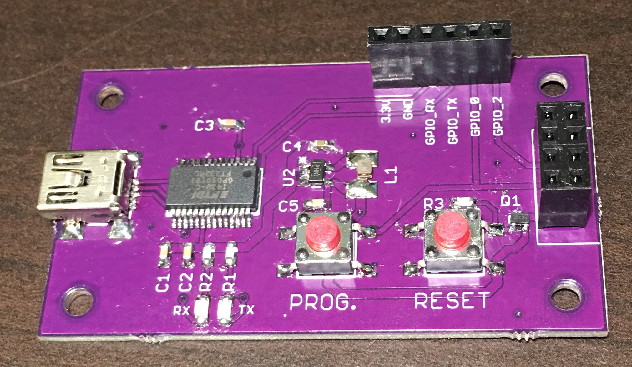
The clock is controlled using an ATmega328, whose only task is to grab information from the ESP8266 and control the nixies. After the ESP connects to WiFi and sends the time, the mega controls the nixies via the HV5530, which is a 32-channel shift register. These chips aren’t cheap, but I much preferred to use a part that’s still in production, than using the vintage 74141, which I’ve only been able to find on Ebay. These shift registers are the same as any other serial in shift register, it takes in serial data and outputs parallel when the latch is enabled. The main difference though, is each pin has an N-channel MOSFET on the output, which can leave each of the nixie’s pins floating at 180V, or grounds them. Given that the output is controlled by MOSFETs, and I was switching 180V, my main concern was the supply voltage to switch the FETs. At 3.3V, the Rds might still be a too high, and cause the FETs to have to waste more power than if they were driven with 12V logic. So in order drive the FETs more efficiently, I incorporated five level shifters to convert the 3.3V logic to 12V logic.
The power supply for the nixies, is just a simple boost converter that takes 12V and boost it up to the 180V to supply power to the anode of the nixies. The inductor uses doesn’t need to be that large, just have a saturation current greater than 100mA. To keep size down, I opted to only display one digit at a time, but I’m flashing through fast enough, that they appear to all be on at the same time.
The ESP8266 Code
The ESP8266 has the responsibility of talking to the internet to fetch the time and update the time, simple right? Well yes and no. It was actually easier than I thought to get the time, using the NTP Client example below.
/*

Udp NTP Client

Get the time from a Network Time Protocol (NTP) time server
Demonstrates use of UDP sendPacket and ReceivePacket
For more on NTP time servers and the messages needed to communicate with them,
see http://en.wikipedia.org/wiki/Network_Time_Protocol

created 4 Sep 2010
by Michael Margolis
modified 9 Apr 2012
by Tom Igoe
updated for the ESP8266 12 Apr 2015
by Ivan Grokhotkov

This code is in the public domain.

*/

#include
#include

char ssid[] = "*************"; // your network SSID (name)
char pass[] = "********"; // your network password

unsigned int localPort = 2390; // local port to listen for UDP packets

/* Don't hardwire the IP address or we won't get the benefits of the pool.
* Lookup the IP address for the host name instead */
//IPAddress timeServer(129, 6, 15, 28); // time.nist.gov NTP server
IPAddress timeServerIP; // time.nist.gov NTP server address
const char* ntpServerName = "time.nist.gov";

const int NTP_PACKET_SIZE = 48; // NTP time stamp is in the first 48 bytes of the message

byte packetBuffer[ NTP_PACKET_SIZE]; //buffer to hold incoming and outgoing packets

// A UDP instance to let us send and receive packets over UDP
WiFiUDP udp;

void setup()
{
Serial.begin(115200);
Serial.println();
Serial.println();

// We start by connecting to a WiFi network
Serial.print("Connecting to ");
Serial.println(ssid);
WiFi.begin(ssid, pass);

while (WiFi.status() != WL_CONNECTED) {
delay(500);
Serial.print(".");
}
Serial.println("");

Serial.println("WiFi connected");
Serial.println("IP address: ");
Serial.println(WiFi.localIP());

Serial.println("Starting UDP");
udp.begin(localPort);
Serial.print("Local port: ");
Serial.println(udp.localPort());
}

void loop()
{
//get a random server from the pool
WiFi.hostByName(ntpServerName, timeServerIP);

sendNTPpacket(timeServerIP); // send an NTP packet to a time server
// wait to see if a reply is available
delay(1000);

int cb = udp.parsePacket();
if (!cb) {
Serial.println("no packet yet");
}
else {
Serial.print("packet received, length=");
Serial.println(cb);
// We've received a packet, read the data from it
udp.read(packetBuffer, NTP_PACKET_SIZE); // read the packet into the buffer

//the timestamp starts at byte 40 of the received packet and is four bytes,
// or two words, long. First, esxtract the two words:

unsigned long highWord = word(packetBuffer[40], packetBuffer[41]);
unsigned long lowWord = word(packetBuffer[42], packetBuffer[43]);
// combine the four bytes (two words) into a long integer
// this is NTP time (seconds since Jan 1 1900):
unsigned long secsSince1900 = highWord << 16 | lowWord;
Serial.print("Seconds since Jan 1 1900 = " );
Serial.println(secsSince1900);

// now convert NTP time into everyday time:
Serial.print("Unix time = ");
// Unix time starts on Jan 1 1970. In seconds, that's 2208988800:
const unsigned long seventyYears = 2208988800UL;
// subtract seventy years:
unsigned long epoch = secsSince1900 - seventyYears;
// print Unix time:
Serial.println(epoch);

// print the hour, minute and second:
Serial.print("The UTC time is "); // UTC is the time at Greenwich Meridian (GMT)
Serial.print((epoch % 86400L) / 3600); // print the hour (86400 equals secs per day)
Serial.print(':');
if ( ((epoch % 3600) / 60) < 10 ) {
// In the first 10 minutes of each hour, we'll want a leading '0'
Serial.print('0');
}
Serial.print((epoch % 3600) / 60); // print the minute (3600 equals secs per minute)
Serial.print(':');
if ( (epoch % 60) < 10 ) {
// In the first 10 seconds of each minute, we'll want a leading '0'
Serial.print('0');
}
Serial.println(epoch % 60); // print the second
}
// wait ten seconds before asking for the time again
delay(10000);
}

// send an NTP request to the time server at the given address
unsigned long sendNTPpacket(IPAddress& address)
{
Serial.println("sending NTP packet...");
// set all bytes in the buffer to 0
memset(packetBuffer, 0, NTP_PACKET_SIZE);
// Initialize values needed to form NTP request
// (see URL above for details on the packets)
packetBuffer[0] = 0b11100011; // LI, Version, Mode
packetBuffer[1] = 0; // Stratum, or type of clock
packetBuffer[2] = 6; // Polling Interval
packetBuffer[3] = 0xEC; // Peer Clock Precision
// 8 bytes of zero for Root Delay & Root Dispersion
packetBuffer[12] = 49;
packetBuffer[13] = 0x4E;
packetBuffer[14] = 49;
packetBuffer[15] = 52;

// all NTP fields have been given values, now
// you can send a packet requesting a timestamp:
udp.beginPacket(address, 123); //NTP requests are to port 123
udp.write(packetBuffer, NTP_PACKET_SIZE);
udp.endPacket();
}
Using this code, I was successfully able to get the time from the NTP server. I made some changes to send the time over serial to my ATmega328, which reads the time, and displays it on the nixies. The big modification, was adding in HTML code to generate a user interface, to configure the network settings, NTP server address, and changing the time, which comes in as GMT, to my local time zone. These settings are saved on ESP and automatically read on power up.
The clock resets every night at midnight, which I did by using a system restart command on the ESP and for the mega, I just enabled the watch dog timer and would enter a endless loop without petting the dog to trigger a restart.
Lastly, the code used on the mega isn’t in the friendly Arduino style. The main reason was I’m starting to move away from Arduino, and trying to program in straight C. The only Arduino class I kept was Serial. C is just a much more efficient language, and therefore faster, this way I was able to maximize my refresh rate on my nixie display.