Featured

About Me

Current Resume

I’m an Electrical Engineer, currently working for Xerox in Rochester NY. I graduated in 2013 with my Bachelors of Science in Electrical Engineering with an engineering GPA of 3.2/4.0 from the University at Buffalo.

I’ve had an interest in electronics since I was a baby, there’s a video of me where I’m just starring at the camera in awe. As I got older, I did what most engineers did as kids, I took anything and everything apart to understand how it worked. I learned early on, that taking something apart was easy, but putting it back together in full working order, was much more difficult.

In high school I took my first basic electronics class and knew almost immediately this is what I wanted to do for the rest of my life. By the end of the semester I was pointing out mistakes made in my teacher’s drawings, and creating my own circuit boards at home. It was this teacher that saw my passion and how quickly I was able to pick up new concepts, and she encouraged me to take an independent study in the class the following semester and to apply to engineering school.

While at the University at Buffalo, I joined the IEEE student chapter and took up the role as the go to electronics expert. Students from the club and across the hall in the electronics lab would come to me looking for my help to debug their circuits or to bounce ideas off of for a new project, as well as laying out circuit boards, or teaching them how to design and lay out a board. While being a full time student, and active in IEEE, I was still working 20 hours a week, initially at a Deli in my hometown, but senior year I became a Student Assistant in the Electronics Laboratory helping junior level students build and debug circuits as well as the school’s IT department running ethernet lines, installing and repairing TVs and security cameras.

After graduating in 2013, I started working at Xerox in Rochester NY as a Junior Electrical Engineer in the Specialty Sensors group, where I currently work. My main responsibilities involve consulting with other groups with applications of our sensors, designing test boxes for senor validation, creating GUIs to display prints as they come out of the machine.

Advertisement

Nixie Tube Clock

NTP Nixie Clock
Nixie Clock Setup Page

There’s just something so visually pleasing about seeing the orange glow from vintage nixie tubes. I’ve seen commercially available nixie clocks, and even kits, but they cheaper ones I’ve found are still a couple hundred dollars, so I decided I’d make my own. I’d like to start out by talking about why I work on my various projects. Each project I work on, starts with wanting to know more about a part or using a new type of technology. My pocket amplifier for example, I made because I had a need to increase the power from my iPod, but I also wanted to learn how to make my own circuit boards at home. This clock was my first experience with the ESP8266, and the whole reason I made this clock, was to be able to experiment with this board and scratch the surface at what it can do.

Get the files from Github

A few years ago I bought a VFD clock from Adafruit, but after a couple months the clock would be a few minutes slow. The reason for the drift comes from the crystal oscillator used to keep track of time, even with an accurate crystal, it wasn’t 100% accurate and the error would build each day, until it was a few minutes slow and needed to be reset. For my clock, I wanted to make sure that never happened, and that’s why I decided to use the ESP8266. The WiFi board will talk to a Network Time Protocol (NTP) server and retrieve the current time every day.

The Main Guts


qdyvuyf
Main Board Schematic
rl5myvh
Nixie Board Schematic

The clock is controlled using an ATmega328, whose only task is to grab information from the ESP8266 and control the nixies. After the ESP connects to WiFi and sends the time, the mega controls the nixies via the HV5530, which is a 32-channel shift register. These chips aren’t cheap, but I much preferred to use a part that’s still in production, than using the vintage 74141, which I’ve only been able to find on Ebay. These shift registers are the same as any other serial in shift register, it takes in serial data and outputs parallel when the latch is enabled. The main difference though, is each pin has an N-channel MOSFET on the output, which can leave each of the nixie’s pins floating at 180V, or grounds them. Given that the output is controlled by MOSFETs, and I was switching 180V, my main concern was the supply voltage to switch the FETs. At 3.3V, the Rds might still be a too high, and cause the FETs to have to waste more power than if they were driven with 12V logic. So in order drive the FETs more efficiently, I incorporated five level shifters to convert the 3.3V logic to 12V logic.

The power supply for the nixies, is just a simple boost converter that takes 12V and boost it up to the 180V to supply power to the anode of the nixies. The inductor uses doesn’t need to be that large, just have a saturation current greater than 100mA. To keep size down, I opted to only display one digit at a time, but I’m flashing through fast enough, that they appear to all be on at the same time.

The ESP8266 Code

The ESP8266 has the responsibility of talking to the internet to fetch the time and update the time, simple right? Well yes and no. It was actually easier than I thought to get the time, using the NTP Client example below.

/*

Udp NTP Client

Get the time from a Network Time Protocol (NTP) time server
Demonstrates use of UDP sendPacket and ReceivePacket
For more on NTP time servers and the messages needed to communicate with them,
see http://en.wikipedia.org/wiki/Network_Time_Protocol

created 4 Sep 2010
by Michael Margolis
modified 9 Apr 2012
by Tom Igoe
updated for the ESP8266 12 Apr 2015
by Ivan Grokhotkov

This code is in the public domain.

*/

#include
#include

char ssid[] = "*************"; // your network SSID (name)
char pass[] = "********"; // your network password

unsigned int localPort = 2390; // local port to listen for UDP packets

/* Don't hardwire the IP address or we won't get the benefits of the pool.
* Lookup the IP address for the host name instead */
//IPAddress timeServer(129, 6, 15, 28); // time.nist.gov NTP server
IPAddress timeServerIP; // time.nist.gov NTP server address
const char* ntpServerName = "time.nist.gov";

const int NTP_PACKET_SIZE = 48; // NTP time stamp is in the first 48 bytes of the message

byte packetBuffer[ NTP_PACKET_SIZE]; //buffer to hold incoming and outgoing packets

// A UDP instance to let us send and receive packets over UDP
WiFiUDP udp;

void setup()
{
Serial.begin(115200);
Serial.println();
Serial.println();

// We start by connecting to a WiFi network
Serial.print("Connecting to ");
Serial.println(ssid);
WiFi.begin(ssid, pass);

while (WiFi.status() != WL_CONNECTED) {
delay(500);
Serial.print(".");
}
Serial.println("");

Serial.println("WiFi connected");
Serial.println("IP address: ");
Serial.println(WiFi.localIP());

Serial.println("Starting UDP");
udp.begin(localPort);
Serial.print("Local port: ");
Serial.println(udp.localPort());
}

void loop()
{
//get a random server from the pool
WiFi.hostByName(ntpServerName, timeServerIP);

sendNTPpacket(timeServerIP); // send an NTP packet to a time server
// wait to see if a reply is available
delay(1000);

int cb = udp.parsePacket();
if (!cb) {
Serial.println("no packet yet");
}
else {
Serial.print("packet received, length=");
Serial.println(cb);
// We've received a packet, read the data from it
udp.read(packetBuffer, NTP_PACKET_SIZE); // read the packet into the buffer

//the timestamp starts at byte 40 of the received packet and is four bytes,
// or two words, long. First, esxtract the two words:

unsigned long highWord = word(packetBuffer[40], packetBuffer[41]);
unsigned long lowWord = word(packetBuffer[42], packetBuffer[43]);
// combine the four bytes (two words) into a long integer
// this is NTP time (seconds since Jan 1 1900):
unsigned long secsSince1900 = highWord << 16 | lowWord;
Serial.print("Seconds since Jan 1 1900 = " );
Serial.println(secsSince1900);

// now convert NTP time into everyday time:
Serial.print("Unix time = ");
// Unix time starts on Jan 1 1970. In seconds, that's 2208988800:
const unsigned long seventyYears = 2208988800UL;
// subtract seventy years:
unsigned long epoch = secsSince1900 - seventyYears;
// print Unix time:
Serial.println(epoch);

// print the hour, minute and second:
Serial.print("The UTC time is "); // UTC is the time at Greenwich Meridian (GMT)
Serial.print((epoch % 86400L) / 3600); // print the hour (86400 equals secs per day)
Serial.print(':');
if ( ((epoch % 3600) / 60) < 10 ) {
// In the first 10 minutes of each hour, we'll want a leading '0'
Serial.print('0');
}
Serial.print((epoch % 3600) / 60); // print the minute (3600 equals secs per minute)
Serial.print(':');
if ( (epoch % 60) < 10 ) {
// In the first 10 seconds of each minute, we'll want a leading '0'
Serial.print('0');
}
Serial.println(epoch % 60); // print the second
}
// wait ten seconds before asking for the time again
delay(10000);
}

// send an NTP request to the time server at the given address
unsigned long sendNTPpacket(IPAddress& address)
{
Serial.println("sending NTP packet...");
// set all bytes in the buffer to 0
memset(packetBuffer, 0, NTP_PACKET_SIZE);
// Initialize values needed to form NTP request
// (see URL above for details on the packets)
packetBuffer[0] = 0b11100011; // LI, Version, Mode
packetBuffer[1] = 0; // Stratum, or type of clock
packetBuffer[2] = 6; // Polling Interval
packetBuffer[3] = 0xEC; // Peer Clock Precision
// 8 bytes of zero for Root Delay & Root Dispersion
packetBuffer[12] = 49;
packetBuffer[13] = 0x4E;
packetBuffer[14] = 49;
packetBuffer[15] = 52;

// all NTP fields have been given values, now
// you can send a packet requesting a timestamp:
udp.beginPacket(address, 123); //NTP requests are to port 123
udp.write(packetBuffer, NTP_PACKET_SIZE);
udp.endPacket();
}

Using this code, I was successfully able to get the time from the NTP server. I made some changes to send the time over serial to my ATmega328, which reads the time, and displays it on the nixies. The big modification, was adding in HTML code to generate a user interface, to configure the network settings, NTP server address, and changing the time, which comes in as GMT, to my local time zone. These settings are saved on ESP and automatically read on power up.

The clock resets every night at midnight, which I did by using a system restart command on the ESP and for the mega, I just enabled the watch dog timer and would enter a endless loop without petting the dog to trigger a restart.

Lastly, the code used on the mega isn’t in the friendly Arduino style. The main reason was I’m starting to move away from Arduino, and trying to program in straight C. The only Arduino class I kept was Serial. C is just a much more efficient language, and therefore faster, this way I was able to maximize my refresh rate on my nixie display.

The ESP8266 Programming Board

ESP-01

Lately at work and at home, I’ve spent a lot of time working with the ESP8266. For anyone that’s familiar, it’s a low cost (as low as 3 USD) microcontroller from Espressif with on board 802.11 b/g/n Wi-Fi, with over 10 GPIO, UART, a single ADC, and SPI. Now that it’s programmable in the Arduino IDE, it’s both insanely cheap, and equally easy to program (writing the software at least).

I’ve been working with mainly the ESP-01, for about $3, you only get a UART and two other GPIO, not great, but for the price, it’s still hard to complain. One thing that is worth complaining about though, is wiring the board to program. With my Arduinos, I use an FTDI programmer, which I can switch between 3.3V and 5V logic. However, with the ESP I’m not able to just use the FTDI board. The issue lies with the power; the ESP is just too power hungry. During normal operation, it can draw up to 250 mA, but I typically see about half of that in steady-state.

With USB 2.0, part of the standard is for the device (in this case the FTDI chip) to negotiate with the host (your computer) for power. If it doesn’t negotiate, the computer will only supply up to 100 mA to that device, this is a problem when the ESP draws close to that when it’s being programmed, and the FTDI uses an LDO to convert 5V down to 3.3V. This means that you have to use an external power supply. So I went out to make a programmer that can program the board and supply power from the USB port. Here’s what I ended up with:

ESP-01 Programmer Front
ESP-01 Programmer Back

It’s essentially exactly the same as your standard FTDI breakout board, but instead of using the internal 3.3V LDO, I opted to use a 3.3V buck regulator to increase efficiency and program without hassle, and I also included two buttons:

PROG. – Connected to GPIO_0, and shorts to ground when pressed. On power up, this places the board in programming mode.

RESET – Removes power from the ESP while pressed.

So by pressing and holding PROG. and then momentarily pressing restart, you can boot the board to programming mode. Further more, to make prototyping easier, I broke out power, and the GPIO pins to a header so you can do all of your testing from there, before you deploy the ESP8266.

The full schematic is below along with the design files I made in Eagle, overall the board was under $20 to make, I’ll try and add a bill of materials, but all of my resistors and capacitors are 0603, LEDs are 0805, the inductor for the buck converter was an 0806, and the push buttons are momentary, normally open, 6mm square.

PCB Files

Order directly from OSHpark

ESP8266 Programmer Schematic

Arducard – The Arduino Business Card

Arduino Business Card Front
Arduino Business Card Back

Why did I make such an expensive business card?

Finding a job is tough. Even if you’re a perfect fit for a job, it doesn’t guarantee that you’ll get an interview, let alone get you the job. Searching google for “how to get a job as *insert job title here*”, will result in a million of pages giving you advice on how to get the job you want. Well, this post is going to make it 1,000,001, even though the point of this blog post isn’t a tutorial on how to get you a job.

Just because you’re a great fit, doesn’t mean you’ll get an interview. It takes more than being a good fit, you have to also be MEMORABLE. If nothing in your resume or cover letter leaves HR or your potential future manager, anything for them to remember you for, chances are slim that you’ll ever hear from them. This blog for example is to serve three purposes. The first is to help document my projects, and to remember all of the things I work on at home. The second, is to help you, the reader, who may want to work on a similar project, and see how I did it, learn from some of the mistakes I’ve made, and inspire you to maybe work on something similar. Lastly, I link this blog in my cover letter, as a way to try and be memorable and show the employer that I am competent and  to hopefully make them think “Who should we give a call to? What about that guy that has that blog and even typed out my exact thought bubble?”

But the main point of this blog isn’t for marketing, it’s to document my projects. A few years ago I came across a cool project, the Arduboy, a credit card sized Game Boy powered using Arduino. I liked the idea behind the Arduboy, and they added a lot of functionality for their kickstarter, but I had one major issue with it, it wasn’t mine. That’s the problem with makers, we don’t like buying products, we get our joy from making them. I didn’t care if it wasn’t as good, it was about doing it myself and customizing it to my liking, and so the Arducard was born.

How I did it

The Arducard uses a capacitive touch sensor for classic Nintendo controls a low power OLED display for the screen. The controls and display are connected to the ATmega328P and everything is powered from a single CR2032 coin cell battery with a 3.3V boost converter to regulate the power coming out of the battery as efficiently as possible. Below is the full schematic, and here’s the github repo with the Eagle files, and source code.

Arducard Schematic
Arducard Schematic
Name Part Number Source Cost
BAT1 CR2032 Digikey $0.28
S1 JS102011SAQN Digikey $0.53
L1 MLZ1608M100WT000 Digikey $0.17
C1,C2 C1608X5R0J106M080AB Digikey $0.18
C3,C4,C5
C6,C7
GRM188R71C104KA01D Digikey $0.19
R1 RC0603JR-0710KL Digikey $0.10
R2 RC0603JR-0775KL Digikey $0.10
Y1 CSTCE8M00G55-R0 Digikey $0.46
U1 ATMEGA328P-AU Digikey $3.58
U2 MPR121QR2 Digikey $1.50
U3 TPS61097-33DBVR Digikey $2.34
LCD1 0.96″ OLED SPI Display Module Ebay $6.89
PCB Circuit Board OSH Park $11.62
Total: $27.13

You can play just about any game that uses less than 30kB of flash and 2k of RAM, but I opted for Snake 360, it’s a classic game, and it’s difficult enough that it makes the player want to keep playing, and the whole time they’re playing, they’re starring at your contact information. I wasn’t a fan of the layout the Arduboy used, clearly they placed the screen and the buttons to match the original Game Boy, but given the small size, I thought it was important to move the buttons to the either side of the display to make it more comfortable, which is also why I rounded the corners over after I placed my order for the second revision of boards. I used to mill layer to cut out a rectangle the size of the OLED screen, this along with the inverted silkscreen over the A and B capacitive touch buttons, a nice clean look.

One of the things I was most surprised with was the battery life. In the first revision, I just had the battery connected to the 3.3V rail. I ordered a microcontroller to operate down to the last 10% of battery capacity, but overlooked the forward voltage drop that’s used for the display, which is why I added in a boost regulator. On the first revision, battery life was only about half an hour before the screen stopped working. After the boost regulator, I was able to get 10+ hours of game play before the coin cell needed to be replaced. This was one of the projects where I wasn’t looking for a job when I made it, but now that I have a few, when I do go to interviews in the future, it’s something I’ll make sure to have ready to hand out. Of course the major down side to this business card is the cost. I was able to build one of these for around $25, way more expensive than your typical business card. But when you want to stand out, it’s certainly worth it’s weight in gold.

Plasma Speaker

The sound you hear in the video below is coming from the high voltage arc, there is no other speaker being used to generate the sound.

Some Background

In the summer of 2014, a co-worker and  I were planning on attending the Electrostatic Society of America (ESA) conference at the University of Notre Dame. I decided to work on a project to take with me, a plasma speaker.

Most speakers work by using a cone to push air to make sound. A far less efficient way of doing that (but way cooler) is to generate a high voltage arc which also pushes air to make sound. To generate the high voltage, I used a flyback transformer that I pulled out of an old CRT television. Here’s a picture of the board I made, along with the schematic.

Plasma Speaker

How it works

I’m going to explain how the circuit works, but instead of starting from the input and working to the output, this time it might be easier to start at the end. As I said, I used a flyback transformer to generate the high voltage. Instead of using the primary built into the transformer, I wrapped about 10 turns of 20 AWG wire around the ferrite core of the transformer, this gives me an easy way to adjust the output voltage by adding or removing turns on the primary. Flybacks can be a bit nasty though to drive though. The reason they have their name is because some of that high voltage flies back to the primary, which can damage or destroy components connected to the primary. By adding in D1, D2, C4, R5 (MOV), I’m able to suppress the high voltage spikes and keep my MOSFET (IRF840) within a safe drain to source voltage. IC4 is just a MOSFET driver to help switch the FET more efficiently and allowed me to run the speaker longer without overheating.

Every transformer is going to have a frequency range where they operate most efficiently. Linear power supplies are often extremely heavy due to the size of the transformer inside. Those transformers switch at the mains frequencies of 50/60 Hz. If you made the transformer smaller, it would become less efficient at those frequencies and would have to transfer less power from the primary to secondary. In order to get more power out of a smaller transformer, you have to increase the switching frequency to match the transformer. This is why switch mode power supplies are so small and light, because they switch at frequencies a few orders of magnitude higher than what comes out of your wall, so they can use much smaller transformers.

Humans can hear anywhere from about 20 Hz all the up to 20 kHz (lower as we get older), but a flyback transformer is most efficient around 100 kHz. What this means is that I wouldn’t be pass my audio signal directly through the flyback. Instead what I needed to do was use a carrier signal at 100 kHz and modulate the carrier based on the sound from my audio source. And because the carrier is well above human hearing, you won’t need to worry about demodulation to listen to the music. I modulated the audio signal by using the TL949 PWM IC. It works similar to a 555 timer, but it’s much easier to adjust the duty cycle from 0-100%, all you need to do is wire in a resistor and capacitor to set the frequency. By wiring in the audio signal between the input and DTC pin, you’re able to modulate the pulse width based on the audio.

Finally, I used a LM358 to amplify the audio signal, but I had difficulty setting up the offset for the audio source to amplify without severely clipping, which is why in the picture above, I removed IC1 altogether  and shorted pins 2 and 3 of the volume trimmer together.

Active Dummy Load

Wasting power never felt so good

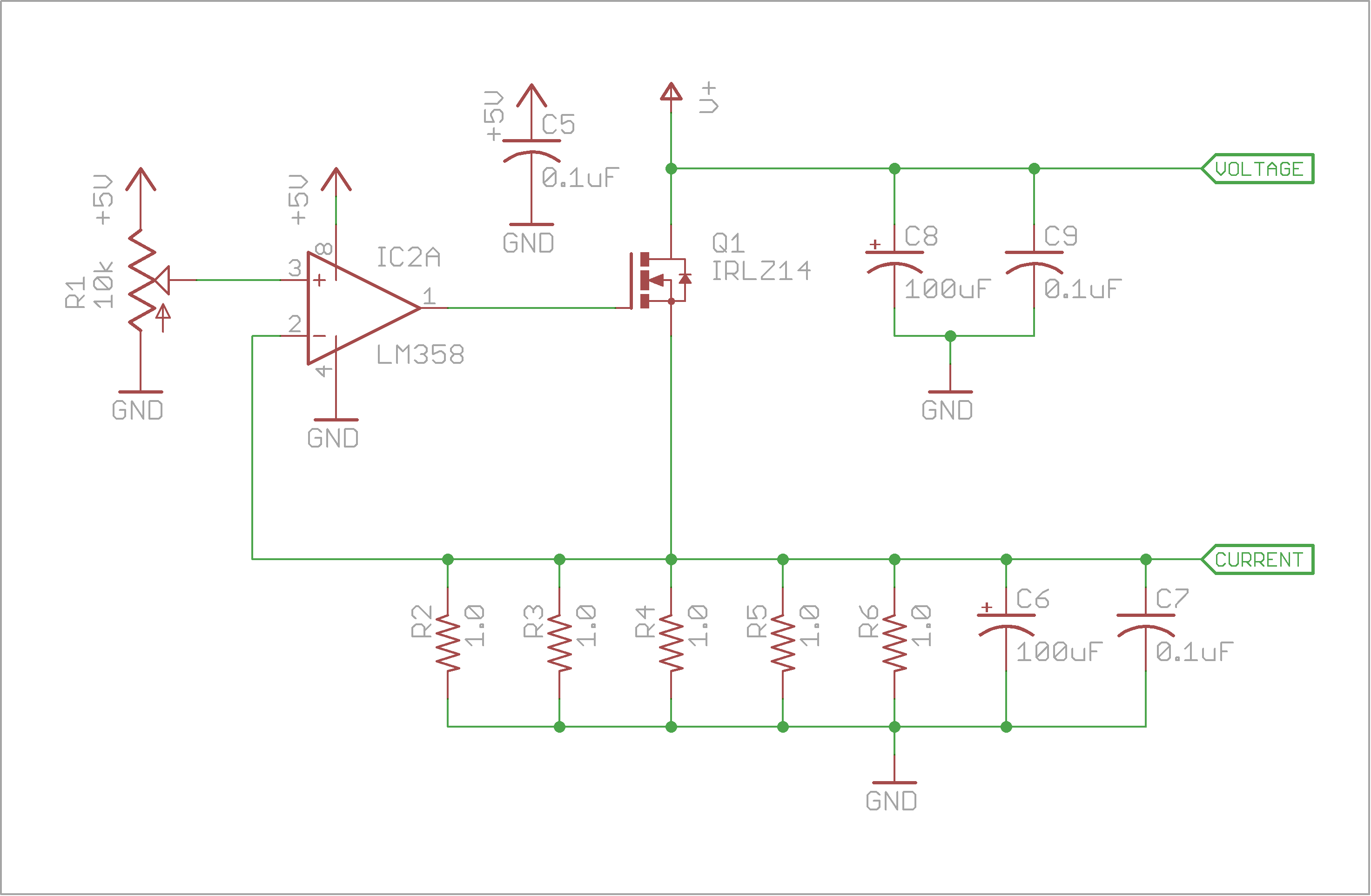
After I built the power supply testing jig, I thought the dummy load side of things could have been better. Before I talk about the changes I wanted to make, let’s first look at the original dummy load.

dummy load(1)

The way this circuit works, is I had an op-amp setup as a comparator, which controls the gate of an N-channel MOSFET. The voltage drop across my five 1Ω resistors, gives me an equivalent resistance 0f 0.2Ω, which gives me a transfer function, where CURRENT = 5*I (Volts). If that voltage drop exceeds the voltage of the wiper of the trimmer pot, current is stopped by the MOSFET, but now that the current is too low, the current is allowed to flow again, which then repeats. The capacitors help to average out the switching and read an analog voltage.

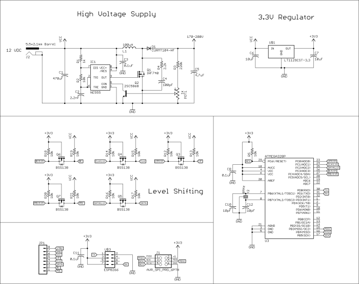
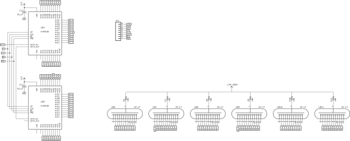
The main goal I wanted in my new design was an easy way to display the current, voltage, and power being dissipated through the dummy load. I could have gotten a cheap panel meter for the voltage and current, but that wouldn’t have helped with the power draw, so I decided to use a 16×2 character LCD driven by an ATmega328. In the original circuit, the current was set using a 10k trim pot on the non-inverting pin of my comparator, but now that I had a microcontroller, I decided to remove it and control it digitally using a rotary encoder. I connected a PWM output to the comparator, using a two-stage low pass filter to convert the duty cycle to an analog voltage. The new circuit is below.

dummy load

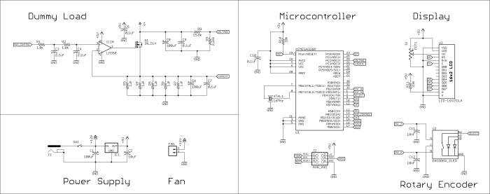
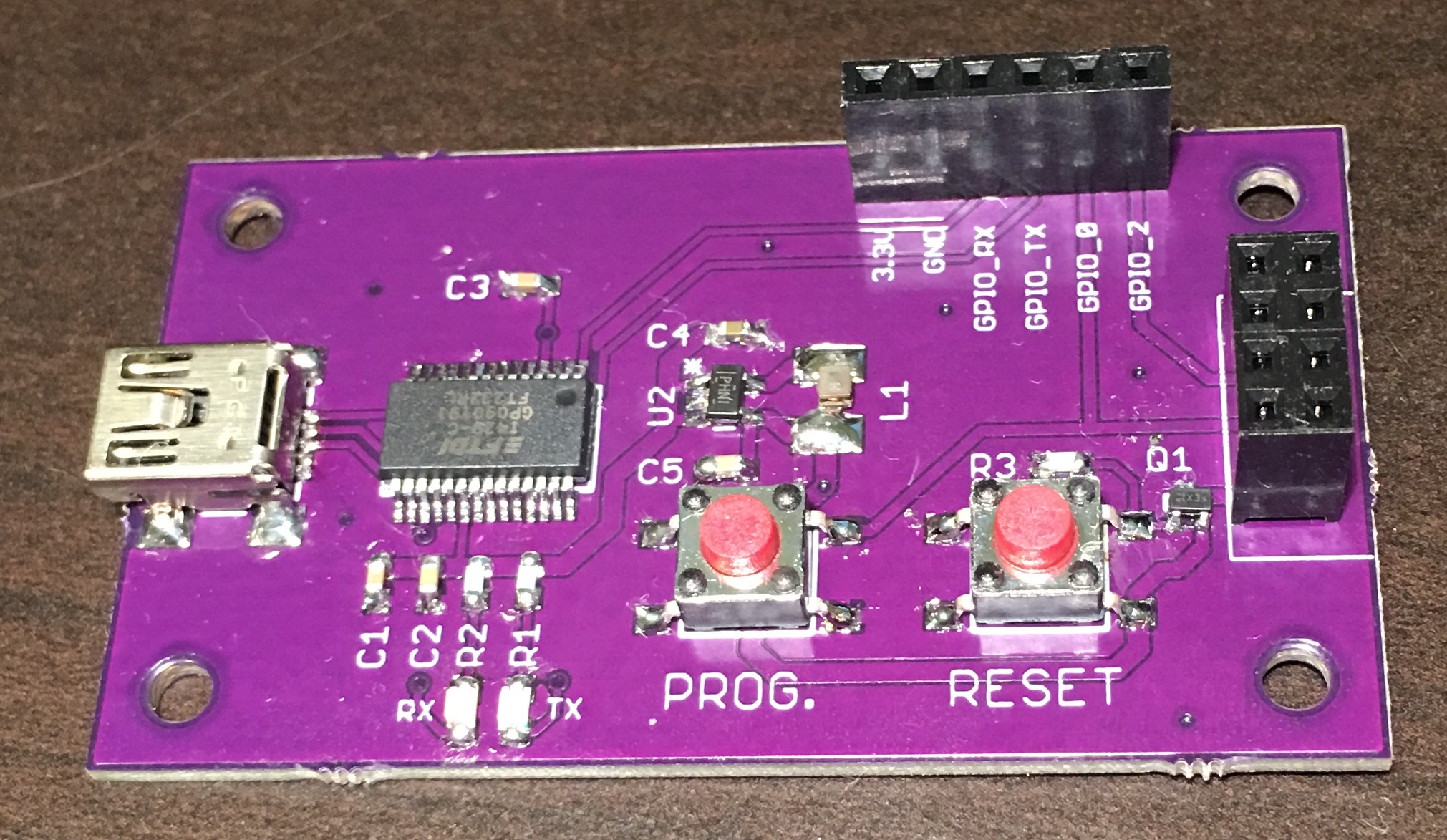
I also increased the size of the heat sink on the MOSFET and added a fan to allow me to connect larger loads without getting the FET too hot. The added benefit of adjusting the current digitally, was that I could now through software configure the dummy load to be not just constant current, but constant power too, by adjusting the current proportionally to any changes in the measured supply voltage at V+.  Here’s a picture of the finished dummy load, with the source code below.

Note on the source code: I made some changes where it was painfully obvious how new to programming I was when I made this. So while it still isn’t an example of my coding today, it should work for those interested in building their own.


#include <LiquidCrystal.h>
#include "TimerOne.h"

#define ENCODER_SELECT 4
#define ENCODER_A 2
#define ENCODER_B 3

#define SUPPLY_VOLTAGE A2
#define SUPPLY_CURRENT A3
#define PWM_CONTROL 9

LiquidCrystal lcd(5,6,7,8,10,A0);

byte ohm[8]= {B00000,B01110,B10001,B10001,B10001,B01010,B11011,B00000};
byte down[8]={B00000,B00000,B00000,B00000,B11111,B01110,B00100,B00000};

byte mode=0, screen_mode, powerOld;
boolean rotating=false;
int lastReportedPos[] = {1,1,1}, encoderPos[] = {0,0,0,0}, pwmValue;
float old_time1, I_set, Iactual, voltage;
byte counter;

// interrupt service routine vars
boolean A_set = false; 
boolean B_set = false;

void setup(){
  lcd.begin(16,2);
  lcd.createChar(1,ohm);
  lcd.createChar(2,down);

  pinMode(ENCODER_A, INPUT); 
  pinMode(ENCODER_B, INPUT);
  pinMode(ENCODER_SELECT, INPUT);
  pinMode(PWM_CONTROL,OUTPUT);
  digitalWrite(ENCODER_A, HIGH);
  digitalWrite(ENCODER_B, HIGH);
  digitalWrite(ENCODER_SELECT, HIGH);

  attachInterrupt(0, doEncoderA, CHANGE);
  attachInterrupt(1, doEncoderB, CHANGE);

  //Start 10bit PWM 
  Timer1.initialize(100);
  Timer1.pwm(9, 0);
}

void loop(){
  Encoder();
  if(mode==0) Menu();
  else if(mode==1) Current(); 
  else if(mode==2) Power();
}


//Rotary Encoder/////////////////////////////////////////////////////////////////////////////////////////////////////////
void Encoder(){
  rotating = true; // reset the debouncer
 
  if (lastReportedPos[mode] != encoderPos[mode]) {
    if(encoderPos[mode]<0)encoderPos[mode]=0; if(mode==0)counter=(encoderPos[0]); lastReportedPos[mode] = encoderPos[mode]; } } //Menu//////////////////////////////////////////////////////////////////////////////////////////////////////////////////// void Menu(){ screen_mode=0; if(!digitalRead(ENCODER_SELECT)) { while(!digitalRead(ENCODER_SELECT)) delay(10); mode=counter; } lcd.setCursor(0,0); lcd.print(" Menu "); if(counter==1) //Current Mode { lcd.setCursor(0,1); lcd.print(" Current >");
  }
  else if(counter==2) //Power Mode
  {
    lcd.setCursor(0,1);
    lcd.print("< Power "); } if(counter>2)counter=2;
  else if(counter<1)counter=1;
}

//Current////////////////////////////////////////////////////////////////////////////////////////////////////////////////
void Current(){
  I_set = encoderPos[mode]/20.00; //Set current adjustment resolution to 50mA

  //Read current
  unsigned int sample=0;
  for(byte i=0;i<200;i++) { sample += analogRead(SUPPLY_CURRENT); } Iactual=0.0072*(sample/200.0)+0.0158; if(Iactual>I_set && abs(Iactual-I_set)>0.005){
    pwmValue--;
    if(pwmValue<0)pwmValue=0;
    Timer1.pwm(9,pwmValue);
  } 
  else if(Iactual<I_set && abs(Iactual-I_set)>0.005){
    pwmValue++;
    if(pwmValue>1023)pwmValue=1023;
    Timer1.pwm(9,pwmValue);
  }
 
  //Update Display
  lcd.setCursor(0,0);
  lcd.print(" ");
  lcd.setCursor(0,1);
  lcd.print("I = ");
  if((millis()-old_time1)<=250){ //update display every 250ms
    if(I_set < 1){
      I_set *= 1000;
      lcd.setCursor(4,1);
      lcd.print(I_set,0);
      lcd.print(" mA ");
    }
    else{
      lcd.setCursor(3,1);
      lcd.print(I_set,3);
      lcd.print(" A ");
    }
  }
  else{
    if(Iactual < 1){
      Iactual *= 1000;
      lcd.setCursor(4,1);
      lcd.print(Iactual,0);
      lcd.print(" mA ");
    }
    else{
      lcd.setCursor(3,1);
      lcd.print(Iactual,3);
      lcd.setCursor(8,1);
      lcd.print(" A ");
    }
 }
 
  if(!digitalRead(ENCODER_SELECT)){ //Go back to menu
    while(!digitalRead(ENCODER_SELECT)) delay(10);
    encoderPos[mode]=0;
    mode=0;
    Timer1.pwm(9,0);
  }
}

//Power//////////////////////////////////////////////////////////////////////////////////////////////////////////////////
void Power(){
  lcd.setCursor(13,1);
  ////////////Read Voltage//////////////////// 
  unsigned int sample=0;
  for(byte i=0;i<200;i++)
  {
    sample += analogRead(SUPPLY_VOLTAGE);
  } 
  voltage=0.1107*(sample/200.0)+0.249;
  ////////////Read Current//////////////////// 
  sample = 0;
  for(int g=0;g<200;g++) { sample += analogRead(SUPPLY_CURRENT); } Iactual=0.0072*(sample/200.0)+0.0158; float power = Iactual*voltage; //////////////////////////////////////////// if(encoderPos[mode]==0){ pwmValue=0; Timer1.pwm(9,pwmValue); } if(encoderPos[mode] != powerOld){ pwmValue=0; powerOld=encoderPos[mode]; } else if(power>encoderPos[mode] && abs(power-encoderPos[mode])>0.1){
    pwmValue-=1;
    if(pwmValue<0)pwmValue=0;
    Timer1.pwm(9,pwmValue); 
  }
  else if(power<encoderPos[mode] && abs(power-encoderPos[mode])>0.1){
    pwmValue+=1;
    if(pwmValue>1023)pwmValue=1023;
    if(abs(power-encoderPos[mode])>0.2)Timer1.pwm(9,pwmValue);
  }
 
  //Update Display
  lcd.setCursor(0,0);
  lcd.print(" Power ");
  lcd.setCursor(0,1);
  if(screen_mode==0)
  {
    lcd.setCursor(0,1);
    lcd.print(" ");
    screen_mode=1;
  }
  lcd.print("P = ");
  lcd.setCursor(4,1);
  if(power<10.0 || encoderPos[mode] < 10.0)lcd.print(" ");
  if((millis()-old_time1)<=250){
    lcd.print(encoderPos[mode]);
    lcd.print(" ");
  }
  else{
    lcd.print(power);
    lcd.print(" "); 
  }
  lcd.setCursor(10,1);
  lcd.print("W ");
 
  if(!digitalRead(ENCODER_SELECT)){ //Go back to menu
    while(!digitalRead(ENCODER_SELECT)) delay(10);
    encoderPos[mode]=0;
    mode=0;
    Timer1.pwm(9,0);
  }
}

/////////////////////////////////////////////////////////////////////////////////////////////////////////////////////////
void doEncoderA(){
  if( digitalRead(ENCODER_A) != A_set ){
    A_set = !A_set;
    // adjust counter + if A leads B
    if ( A_set && !B_set ){
      encoderPos[mode]++;
      old_time1=millis();
    }
    rotating = false;
  }
}

void doEncoderB(){
  if( digitalRead(ENCODER_B) != B_set ){
    B_set = !B_set;
    // adjust counter - 1 if B leads A
    if( B_set && !A_set ){ 
      encoderPos[mode]--;
      old_time1=millis();
    }
    rotating = false;
  }
}

Electromagnetic Levitator

Trying to fight gravity

Here’s another project that was done in college. In one of my senior design classes, we had to build a project that just had a sensor of some kind. I was in a team with four other people, two were undergraduates like myself, and the other two were graduate students. One of the grad students came up with the idea of measuring the magnetic field intensity, and displaying the strength on an LCD screen. The idea was nice, but too basic for our liking. How would we, or the rest of the class know the measurement was even accurate? We had to come up with better idea.

I remember seeing projects on instructables about levitating a magnet in the air using line break sensors to control an inductor, like the one in the picture below, and thought “why can’t we do this with a magnetic field sensor?” And so the idea was born.

We came across consumer products that did this and we wanted to try it ourselves. I took out my Arduino, and started writing some code. The concept was almost the same as the line break sensors:

We would read the analog voltage from the ratiometric hall effect sensor, and get set a set point. If the value exceeded the set point, cut power to the inductor, or if it was below the set point, turn the power back on to the inductor.

There was a problem with this approach though, it was inherently unstable. And didn’t work at all. Our experiments progressed, using pulse-width-modulation (PWM), here we would increase power until the force on the magnet exceeded the force of gravity, and then we would reduce power with each loop iteration until the magnet crossed back over the set point. This time it would hover for a second, before the magnet dropped to the table, or stuck to the inductor.

Our final iteration was successful. What we did was check if the magnet was in the range of the set point. Just as before, if the magnet was too close, we would reduce the duty cycle, and if it was too low, we would increase the duty cycle, but if it was in the “Goldilocks” range, we wouldn’t make any adjustments. Here are the results of our third experiment:

As you can see, there are still oscillations, but it was stable enough that it wouldn’t fall outside of the range we set. Here’s the original code we used to get it up and running, it’s incredibly simple.

// A0 - Hall Effect Sensor Output
// D5 - MOSFET Gate

byte pwmValue = 100;

void setup()
{
 TCCR0B = TCCR0B & 0b11111000 | 0x02; //Increase PWM frequency to 7.8kHz
 pinMode(5, OUTPUT); //sets digital pin 5 as Output and connect to gate of mosfet
}

void loop()
{
 int Hall=analogRead(A1); //0-1024
 if(Hall>920)  //if magnet is too high, reduce PWM until lower threshold is reached
 { 
   pwmValue-=5; 
   analogWrite(5,pwmValue); 
 } 
 else if(Hall<900) //if magnet is too low, increase PWM until upper threshold is reached
 { 
   pwmValue+=5;
   analogWrite(5,pwmValue); 
 }
}

If I were to build this again, there’s a couple of things I would want to add. The first, I would want to impliment a PID loop, to remove the oscillations and get smooth positioning. None of us in the group at the time really had any clue how to program, so a lot of the time was spent figuring out how to change the default PWM frequency and learn how to do embedded programming. The second change I would make would be to add in a second sensor on the other side of the inductor. The main problem with one sensor, is that you’re not only measuring the strength of the magnetic field from the magnet, but also the magnetic field from the inductor, which probably helped create some of the oscillations in the first place.

Nanosat

While studying at the University at Buffalo, I had the opportunity to join my school’s Nanosat program. The University Nanosatellite Program (UNP), is a university competition run my NASA and the Air Force Research Laboratory (AFRL) where universities are given $150k to build a nanosatellite which solves various problems in space. Out of the dozen schools selected to participate in the program, the first place team at the end of the two years of building and design reviews, gets a ride into space with their spacecraft. Our satellite, GLADOS (GLint Analyzing Data Observation Satellite), had the mission to identify and track space debris orbiting the Earth and radio back with the data which can be tracked by other satellites or the Space Fence.

When I was a member, it was our first time in the UNP, and learning as you go in an aerospace engineering project isn’t easy. Our power systems team went through multiple iterations for power generation and regulation. The initial camera that was selected was nearly half of our budget and consumed a huge of power. I was a member of the power and electrical ground support subsystems, and part of my responsibility was trying to design the solar panels to generate enough power to recharge the batteries in as short of a time as possible. One of our power systems members was designing the circuits to regulate the voltage going to the battery charger, and split the battery rail to the various voltages throughout the satellite.

The first iteration was honestly, just terrible. They wanted me to create a solar panel that had every solar cell in parallel, the reasoning being that if one cell is damaged or breaks, it doesn’t take out multiple cells with it. At the time we were using TASC solar cells which have these characteristics:

tasc

At peak power, they have around 2.19V of potential, so the boost converters wouldn’t have been difficult to design for the low power loads, but the larger loads, ie the camera, would need a huge amount of work to design, not to mention the trace widths and wire needed to minimize the voltage drop and heat, were just too unrealistic.  After that power regulation was redesigned, I was able to create a prototype of our smallest panel:

The TO-46 in the middle is a LM35 to sense when our panels are getting too hot and to turn away from the Sun. In hindsight, I don’t know what I used the highest possible rated sensors I could find, 150°C, and used a metal can to tie to ground to try and protect from the radiation, but a thermocouple on the opposite side, probably would have been a better option.

And because we were designing our own regulators, I also created an efficiency logger to use as a tool for testing our power regulation circuits and track their performance. In the video below, I made a video for a independent study using the circuit to track the efficiency of a common linear regulator at various sized loads and deltas between input and output voltage. Video is a little tough to watch, it was one of the first videos I made, and the nerves are painfully obvious as the camera shakes.

I also had the opportunity to go to Boulder Colorado for Student Hands-On Training (SHOT), where we had to build a payload for a weather balloon to test part of the satellite. For most groups, including ours, we were testing part of our communications system, and I went along to design the electronics, mainly the power regulation from the battery, as well as the heaters, GPS tracking, and data logging.

fvudj3p

This is our payload with all the electronics stuffed inside.

1iMboMx

Here’s the ground distance traveled vs elevation. You can see the point at with the balloon popped right around 85,000ft. Finally, below is the video we took with our two, on-board cameras:

Unfortunately, a lot of this was all wasted effort. As more research was done looking for less expensive equipment in other subsystems, and we received donations in equipment, that allowed GLADOS to get an upgrade to commercially available, flight-ready solar panels and boards to handle the power distribution. But this was all just part of the growing pains of such a project. I was part of the conversation on navigating away from custom made hardware, and moving towards commercially available and products that were in our price range, and agreed that it was for the best of the project to convince the design reviewers that we had a satellite that was worthy of flight. In the end, we didn’t win, but NASA did continue to fund GLADOS for a ride into orbit in the near future.

Pocket Headphone Amplifier

If it’s too loud, you’re too old.

…older me is wishing it wasn’t so loud though.

This is one of the first circuit boards I’ve made back in the winter of 2006/2007. Back in high school I rode the bus to and from school and to drown out the noise on the bus, I needed more audio power.

Originally I was looking at the CMoy pocket amplifier:

OPA2134PA-CMoy-Headphone-Amplifier-Schematic

I had one issue with the design though, two 9V batteries, stuffed into an Altoids tin, took up a lot of space, and left very little room for the actual circuit board. I searched digikey, looking for an amplifier that would allow me to use just a single battery, and provide at least 1/2W per audio channel. After a bit of searching, I found the TDA2822 and just used the typical application circuit in the datasheet:

tda2822

The only modification I had to make was to replace the 10k pull-down resistors on the inputs, with a dual-gang log pot to give me volume control. After that I designed the PCB using Express PCB at the time, and then using a sharpie, I drew the CAD design on to the copper clad and etched the board. And here’s how it turned out: