
Lately at work and at home, I’ve spent a lot of time working with the ESP8266. For anyone that’s familiar, it’s a low cost (as low as 3 USD) microcontroller from Espressif with on board 802.11 b/g/n Wi-Fi, with over 10 GPIO, UART, a single ADC, and SPI. Now that it’s programmable in the Arduino IDE, it’s both insanely cheap, and equally easy to program (writing the software at least).
I’ve been working with mainly the ESP-01, for about $3, you only get a UART and two other GPIO, not great, but for the price, it’s still hard to complain. One thing that is worth complaining about though, is wiring the board to program. With my Arduinos, I use an FTDI programmer, which I can switch between 3.3V and 5V logic. However, with the ESP I’m not able to just use the FTDI board. The issue lies with the power; the ESP is just too power hungry. During normal operation, it can draw up to 250 mA, but I typically see about half of that in steady-state.
With USB 2.0, part of the standard is for the device (in this case the FTDI chip) to negotiate with the host (your computer) for power. If it doesn’t negotiate, the computer will only supply up to 100 mA to that device, this is a problem when the ESP draws close to that when it’s being programmed, and the FTDI uses an LDO to convert 5V down to 3.3V. This means that you have to use an external power supply. So I went out to make a programmer that can program the board and supply power from the USB port. Here’s what I ended up with:
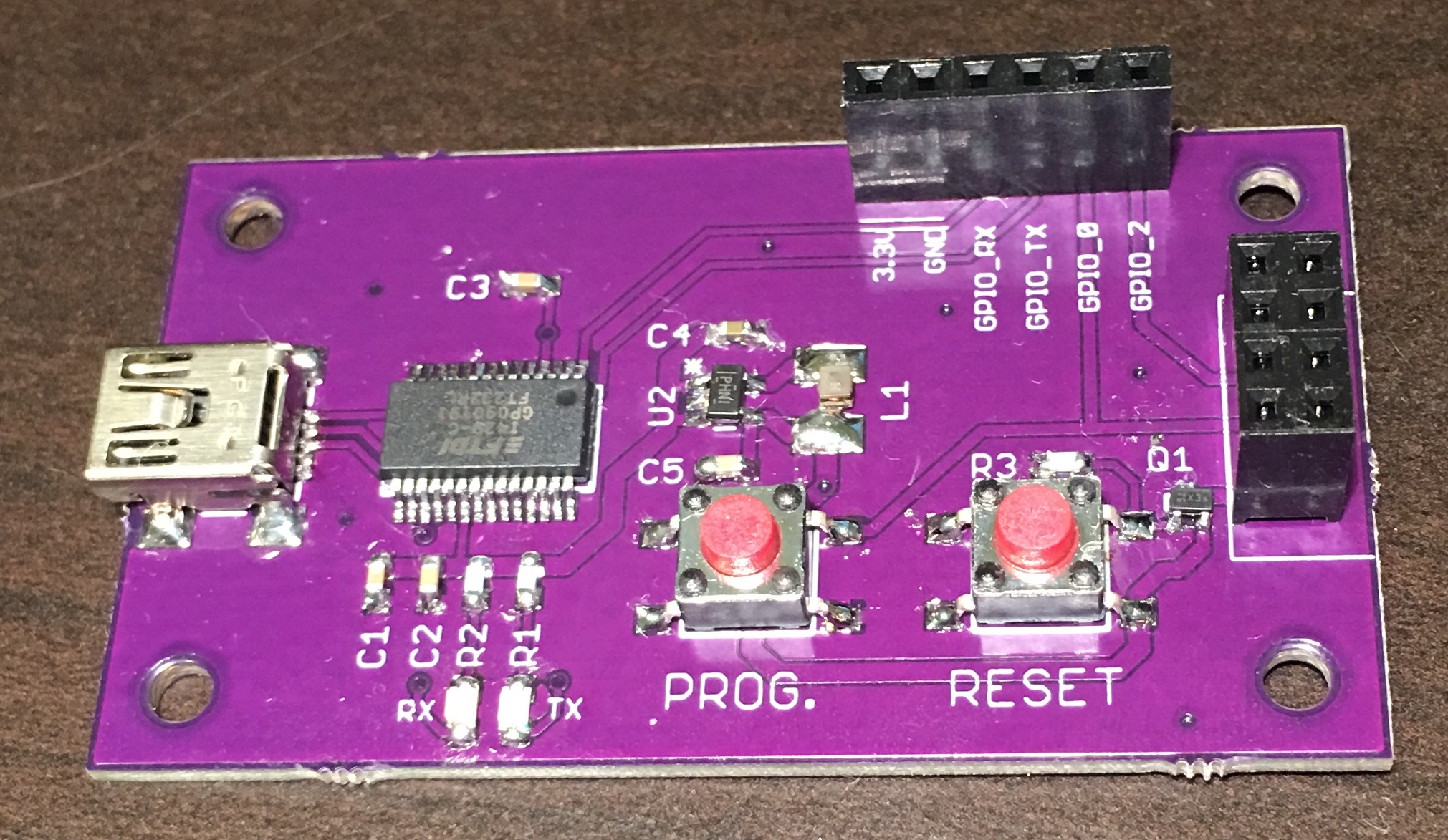

It’s essentially exactly the same as your standard FTDI breakout board, but instead of using the internal 3.3V LDO, I opted to use a 3.3V buck regulator to increase efficiency and program without hassle, and I also included two buttons:
PROG. – Connected to GPIO_0, and shorts to ground when pressed. On power up, this places the board in programming mode.
RESET – Removes power from the ESP while pressed.
So by pressing and holding PROG. and then momentarily pressing restart, you can boot the board to programming mode. Further more, to make prototyping easier, I broke out power, and the GPIO pins to a header so you can do all of your testing from there, before you deploy the ESP8266.
The full schematic is below along with the design files I made in Eagle, overall the board was under $20 to make, I’ll try and add a bill of materials, but all of my resistors and capacitors are 0603, LEDs are 0805, the inductor for the buck converter was an 0806, and the push buttons are momentary, normally open, 6mm square.

